
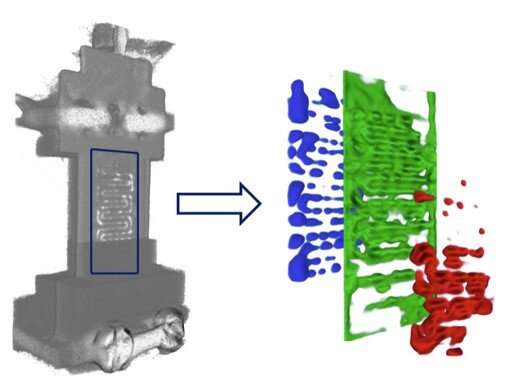
 develops over time during the start-up of the fuel cell. The water increases until a state of equilibrium between water accumulation and degradation is reached. Credit: HZB")
Teams from Helmholtz-Zentrum Berlin (HZB) and University College London (UCL) have visualized the water distribution in a fuel cell in three dimensions and in real time for the first time by evaluating neutron data from the Berlin Experimental Reactor shut down in 2019. The analysis opens new possibilities for more efficient and thus more cost-effective fuel cells.
“In a fuel cell, hydrogen and oxygen are combined to form water. This produces electrical energy,” explains Ralf Ziesche from the imaging group at HZB. “Probably the most important component inside the fuel cell is the membrane.” It is only about 20 micrometers thick (half as wide as a human hair) and connected with various functional layers to form a separation area about 600 micrometers wide inside the fuel cell.
“The membrane composite snatches the electrons from the hydrogen atoms. Only the hydrogen nuclei—the protons—can pass through the membrane.” The electrons, on the other hand, flow off via an electrical connection and are used as an electric current. Air is let in on the other side of the separating wall. The oxygen it contains reacts with the protons that come through the membrane and the electrons that flow back from the other side of the electric circuit. Pure water is produced.
The function of channels
“Some of the water is discharged. Another part must remain in the fuel cell, because the membrane must not dry out,” Ralf Ziesche explains. “But if there is too much water in it, the protons can no longer penetrate the membrane. Dead areas develop at these points, and the reaction can no longer take place there. The efficiency of the entire fuel cell drops.”
To allow hydrogen, air and water to flow in and out, tiny channels are milled into metal plates on both sides of the membrane. These channels can be used to optimize fuel cells and increase efficiency. Hereby, the channel design is the key for a balanced cell wetting and optimal efficiency.
Neutrons for the detection of water
To do this, it is advantageous to have as accurate a picture as possible of the water distribution within the channels. This was the goal of a collaboration between the research group from the Electrochemical Innovation Lab (EIL) at University College London (UCL) and HZB.
“In principle, we subjected the fuel cell to computed tomography, as it is used in medicine,” explains Nikolay Kardjilov from the imaging group at HZB. But while X-rays are used for medical analyses, Nikolay Kardjilov and his team preferred to use neutron radiation. “Because X-rays provide far too low an image contrast between hydrogen and water on one side and the metal structure on the other. Neutrons, on the other hand, are ideal here.”
Rotating fuel cell
This was quite tricky. Because in order to get a three-dimensional image, the radiation source has to go around the object to be imaged. In medicine, this is quite easy to solve. There, the radiation source and scanner rotate around the patient, who is resting on a table.
“But our radiation source was the Berlin Experimental Reactor BER II, where we had set up our imaging station CONRAD. And we can’t simply rotate it around our fuel cell sample,” says Nikolay Kardjilov. But with an engineering trick, his team managed to move the fuel cell, including the supply lines for hydrogen and air, the discharge line for water and the electric cables, into the neutron beam. “Until now, neutron imaging has only been able to produce two-dimensional images from inside the fuel cell. Now, for the very first time, we have also made the water distribution visible in three dimensions and in real time,” the physicist is pleased to report.
The research was published in Nature Communications.
More information: Ralf F. Ziesche et al, High-speed 4D neutron computed tomography for quantifying water dynamics in polymer electrolyte fuel cells, Nature Communications (2022). DOI: 10.1038/s41467-022-29313-5
Citation: Water distribution in fuel cells made visible in 4D (2022, June 3) retrieved 3 June 2022 from https://techxplore.com/news/2022-06-fuel-cells-visible-4d.html
This document is subject to copyright. Apart from any fair dealing for the purpose of private study or research, no part may be reproduced without the written permission. The content is provided for information purposes only.